|
|
| |
FACILITIES
|
|
 |
Optics and
Vortex Rings
|
|
| |
|
|
| |
|
|
|
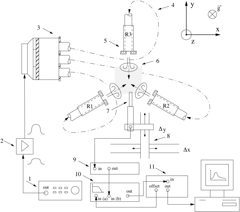
Schematics of the experimental set-up. A function
generator
(1) provides the driving signal to a bipolar amplifier (2). The
amplified signal pushes the piston in the pressure manifold (3)
connected to 3 identical hydraulic hoses (4) that transmit a pressure
pulse into each vortex generator of exit diameter D0=1.5 cm (5). Vortex
rings (6) of diameter D are created simultaneously, symmetrically and
with great repeatability. Fluid velocity is measured with a hot-wire
anemometer (7,9) in a Cartesian spatial window of square grid size
(±5D0, ±5D0) controlled by a three-axis stepper motor
system (0.48 mm/rev). (8) A preamplifier SR560 lowpass filter the
signal which is acquired with a data acquisition card DT9804.
|
|
| |
 |
|
|
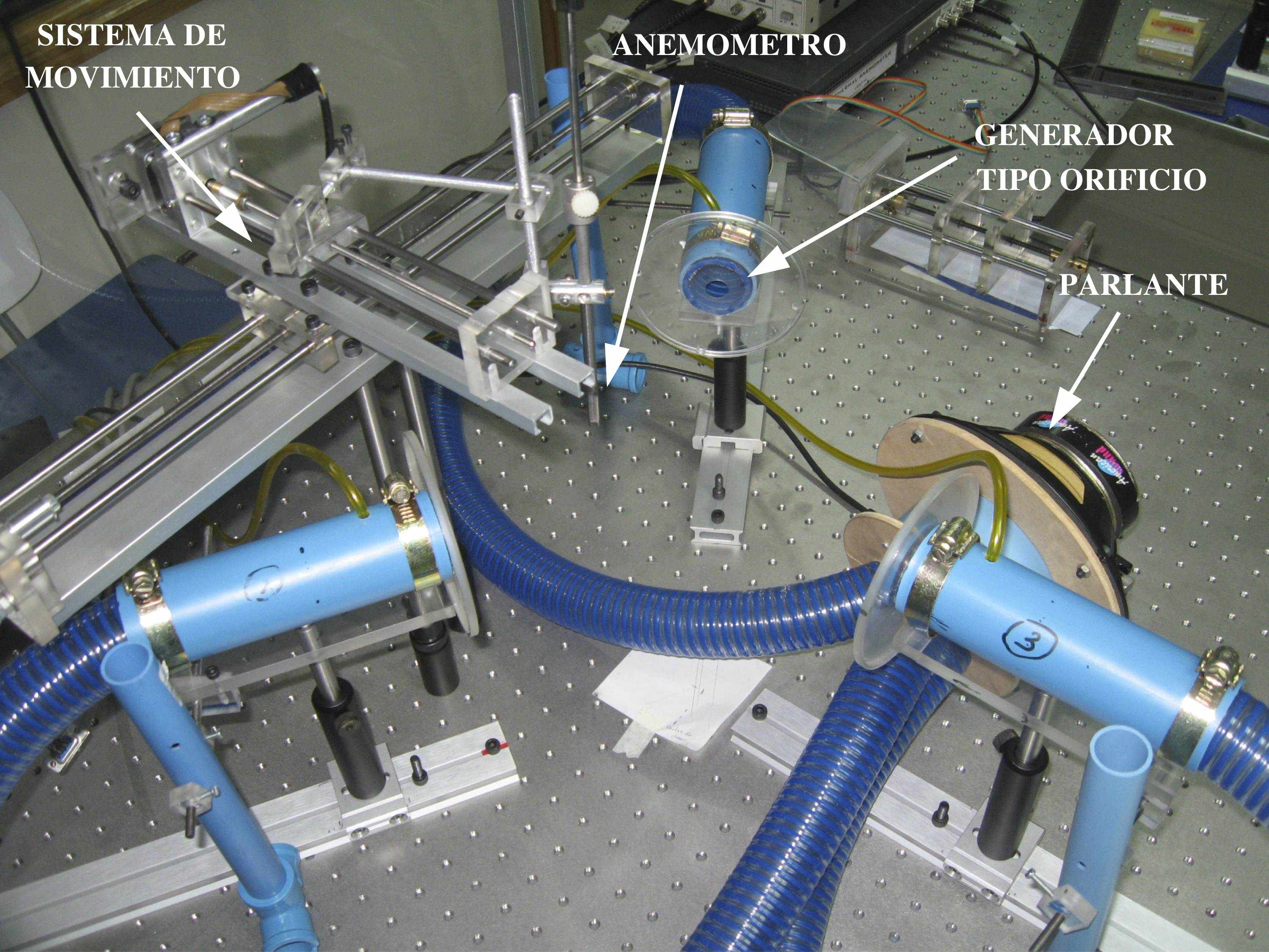
Details of
the experiment performed in air. 3 vortex ring generators at
120 degrees driven by a loudspeaker. |
|
|
 |
|
|
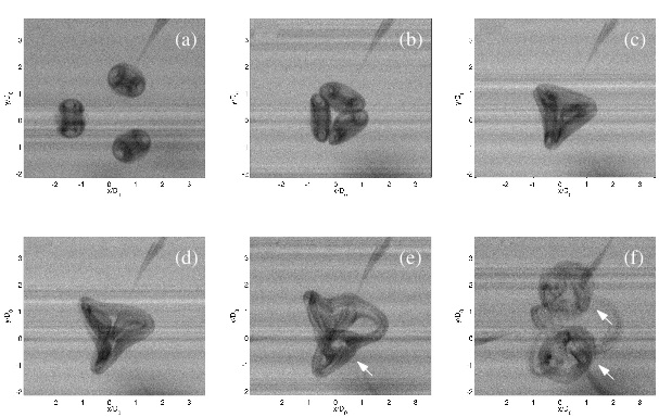
3D view of the
collision using ink visualisation. In this case three vortex rings were
created in water and tagged with ink which is transported as a passive
scalar into the collision region. Arrows indicate vortex rings formed
aftercollision. (a)t=0.566s,(b)t=0.733s,(c)t=0.8s,(d)t=0.9s,(e)
t=1.033s,(f)t=1.8s. Re=250,D=0.42cm. |
|
|
|
|